Ansal
The project was developed during the CMLS course at Politecnico di Milano by me, Alessandro Manattini, and Salvatore Benvenuto Zocco. It is, in a way, a continuation of what I had implemented here. A demo video is also available:
0. Feature summary
The goal we set for ourselves was to provide small groups of musicians with a complete tool to expand their musical possibilities and play as if they were a full band.
To achieve this goal, we implemented the following modules:
- Polyphonic MIDI Phase Vocoder (JUCE): allows simulating vocal harmonies, enriching the musical landscape.
- Polyphonic Synthesizer: offers numerous features, including mono mode, keyboard split, low-pass filter (LPF), octave shifting, pitch shifting, and drum sequences, which will be detailed later.
Note: these two instruments are interconnected. The Vocoder is accessible through the Synth interface, and the notes received by the Synth are forwarded to the Vocoder. This configuration allows a single person to play both instruments “effortlessly”.
- Small suite of Guitar Effects: uses pitch recognition to identify the root notes of the chords being played, allowing a guitarist to “double” their guitar or to “play guitar and bass”.
The functionality of the modules can be modified through the graphical interface or through MIDI command mapping, as will be shown later.
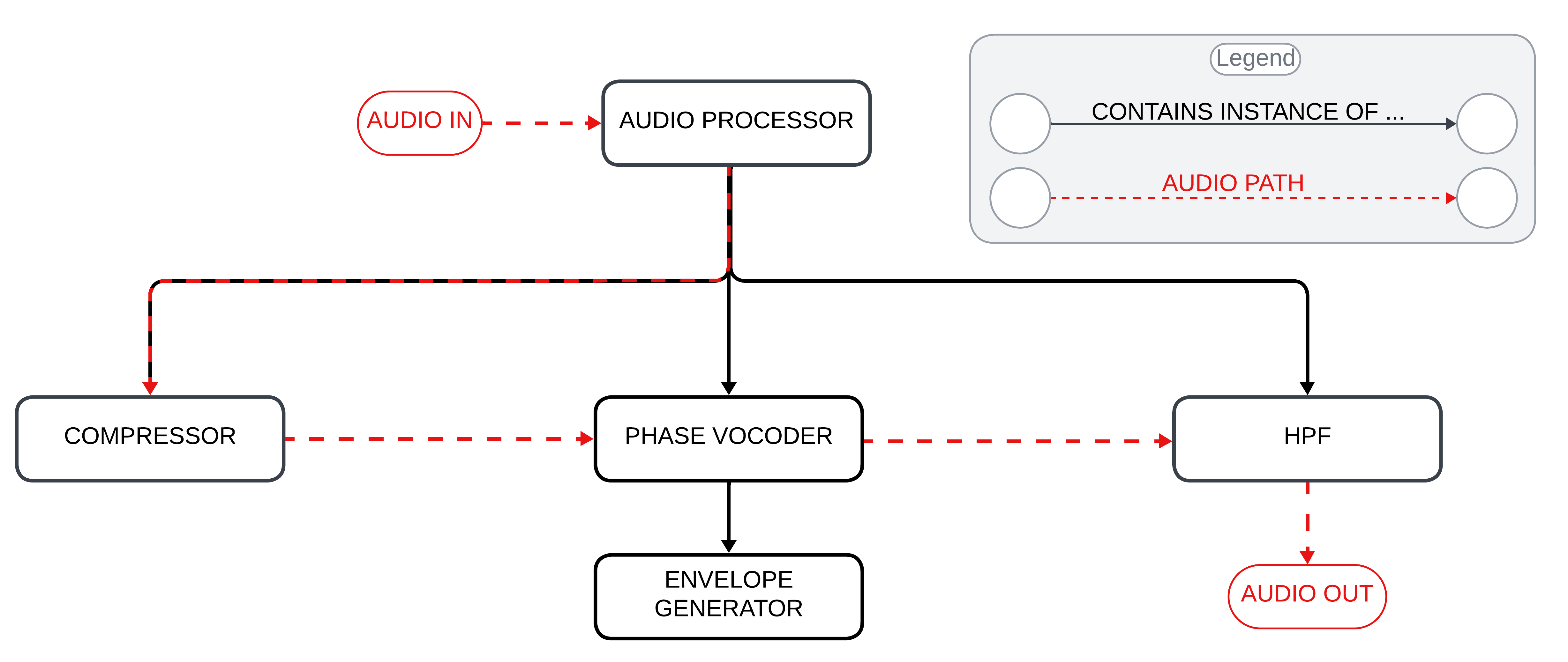
1. Vocoder module
The vocoder implemented in this project is a polyphonic K-voice vocoder (where K is a parameter editable in the private variables in PluginProcessor) controlled via MIDI.

It works as follows:
- Audio input: audio enters through the microphone input into PluginProcessor. Here it is normalized (using the SimpleCompressor class) to ensure a stable input signal level.
- Audio and MIDI processing: the processBlock method reads the incoming audio buffer and the MIDI input. For each MIDI note read, it activates one of the K voices and assigns it to process the audio buffer at the specific frequency of the MIDI note.
- Voice processing: each vocoder voice (PhaseVoc class) processes the audio buffer using the following “leaky autocorrelation” formula:
\(R_{l,n} = (1 - k) R_{l,n-1} + k x_n x_{n-l}\)
Where:
- $R_{l,n}$: leaky autocorrelation at delay $l$ and time $n$.
- $R_{l,n-1}$: leaky autocorrelation at delay $l$ and the previous time step $n-1$.
- $x_n$: input signal at time $n$.
- $x_{n-l}$: input signal $l$ steps before $n$.
- $k$: leakiness constant, typically around $0.001$. This formula balances past autocorrelation values with new data, allowing the vocoder to adapt to changes in the vocal signal over time.
- Envelope application: to ensure the notes have a pleasing envelope, PhaseVoc applies methods from the EnvelopeGenerator class to the processed audio. After doing so, it returns the buffer containing the processed result to PluginProcessor.
- Passive high-pass filtering: before outputting the audio, PluginProcessor applies a high-pass filter (HighPassFilter class) to the output audio to remove the lowest frequencies and improve intelligibility, if necessary.
The subsequent steps and the class hierarchy related to audio processing are easily deduced from the following diagram:
2. Synth module
The synth module includes numerous functions available to the user, all controllable both via the graphical interface and via MIDI. In addition, the Vocoder described in the previous section is integrated inside the Synth module. This configuration ensures that the MIDI notes used to play the synthesizer are also forwarded to the Vocoder, allowing the voice to be modulated with the same harmonies.

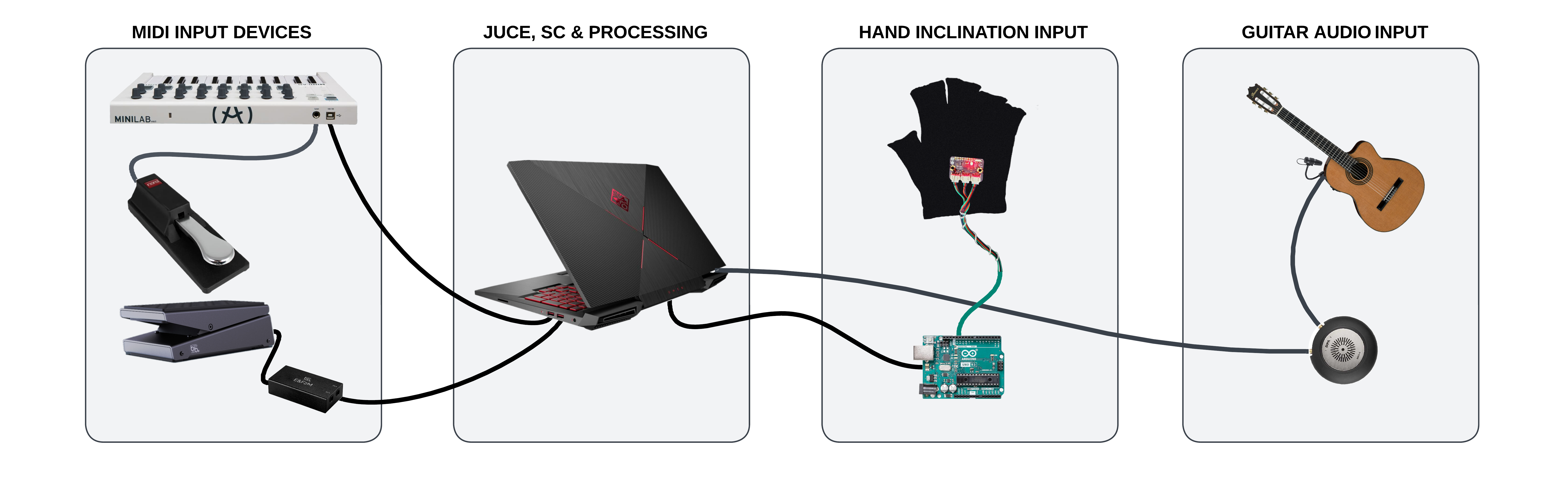
2.1 Synth hardware configuration
The hardware configuration for the synth module is the following:
MIDI input devices
It is possible to edit and control system parameters using various MIDI controllers (details on how this happens will be provided in later sections). The devices include:
- MIDI keyboard (Arturia Minilab configured with this preset).
- Sustain pedal.
- Volume control pedal (not used for volume control).
- Analog-to-MIDI signal adapter (I used this).
Hand tilt input
The system also receives input from the tilt of the keyboardist’s hand. The reason and method to use this input to help control the system will be explained later. The required hardware devices are:
- Accelerometer: mounted on a glove to be worn during performance (I used this).
- Arduino Uno: needed to derive angle data from the accelerometer coordinates and interface the accelerometer with the system.
The system components are connected as shown in the following figure:
2.2 Synthesizer features
The synthesizer offers broad options for configuration and parameter customization. The list of features is detailed in the GUI image at the beginning of the Synth chapter and in the MIDI mapping diagram provided below, so for brevity I will not list them again here.

In the following paragraphs, I will focus on describing the sounds available in the synth and how settings and sounds can be combined to create interesting presets.
2.2.1 Sound patch details
Within the synth, various types of sounds are available for each of the two instruments, improving the versatility of sound customization. Below are the characteristics of each sound patch:
- Rhodes: RHODES1 and RHODES2 emulate the classic Rhodes electric piano using pulse waves to create a rich harmonic spectrum. RHODES1 offers a warm and enveloping sound with an ADSR envelope and a dynamic low-pass filter, enriched by a chorus effect, making it perfect for chordal textures. RHODES2 provides an alternative with a faster attack, an enhanced chorus with longer delay and added reverb, creating a spacious and immersive sound ideal for pads and expressive melodies.
- Bass synth: BASSYN1, BASSYN2, BASSYN3 and BASSIMP cover a wide range of bass sounds. BASSYN1 uses an LFO to modulate pulse width and rate, resulting in a dynamic and evolving sound with automatic panning, suitable for electronic and pop styles. BASSYN2 features slightly detuned sawtooth oscillators combined with a sub-oscillator for a deep and powerful bass sound, with vibrato adding realism and a low-pass filter ensuring punch and clarity. BASSYN3 enhances this design with chorus and light distortion, adding character to the combination of sawtooth oscillators and sub-oscillator, ideal for distinctive bass lines. BASSIMP focuses on simplicity with a single sawtooth oscillator, vibrato, and a low-pass filter, delivering a clean and solid bass tone perfect for essential bass lines.
- Lead and wave synth: LEADSCR, TRIWAVE and SAWWAVE are designed for a variety of uses, from melodic lines to pads and bass. LEADSCR is meant for powerful and sharp lead sounds with a synced sawtooth oscillator and dynamic frequency modulation, with filter cutoff and resonance modulated by envelopes for enhanced expressiveness. TRIWAVE generates a triangle wave with added distortion, providing a distinctive tone controlled by a low-pass filter and an ADSR envelope, ideal for smooth and warm leads and pads with a touch of grit. SAWWAVE produces a classic sawtooth wave, known for its rich and bright harmonic content, with a low-pass filter and an ADSR envelope providing control over timbre and dynamics, making it versatile for leads, pads, and bass lines.
2.2.2 Preset details
- Mono bass, drums, and synth: by activating keyboard split, applying a bass (octave shift -1) on the left section and another synth on the right section, it is possible to simultaneously play a bass and a synth. The mono setting on the left side allows you not to worry about releasing the sustain pedal, letting the pianist focus on coordinating the pedal only with the right hand. By adding a drum sequence and mapping the cutoff frequency of the right-hand synth with the glove or the pedal, you create a very interesting effect (video demonstration).
- Theremin-like configuration: by activating the glove pitch bend mapping for both instruments and connecting the glove y control to the cutoff frequency of the upper synth and the control pedal to the cutoff frequency of the lower synth (octave shift -1), you get unique results (video demonstration).
- Deep synth: using settings similar to the first preset in the list but removing keyboard split, it is possible to obtain this kind of effect.
Note: Keyboard Split can be enabled/disabled as follows:
- By clicking button 1 (top left on the Arturia), the “split selection” mode is enabled. In this mode, the system waits for a key to be pressed. Once done, that key becomes the split point between the left and right sections of the keyboard.
- To remove keyboard split, press button 1 again. Now, both instruments will play simultaneously over the full keyboard range.
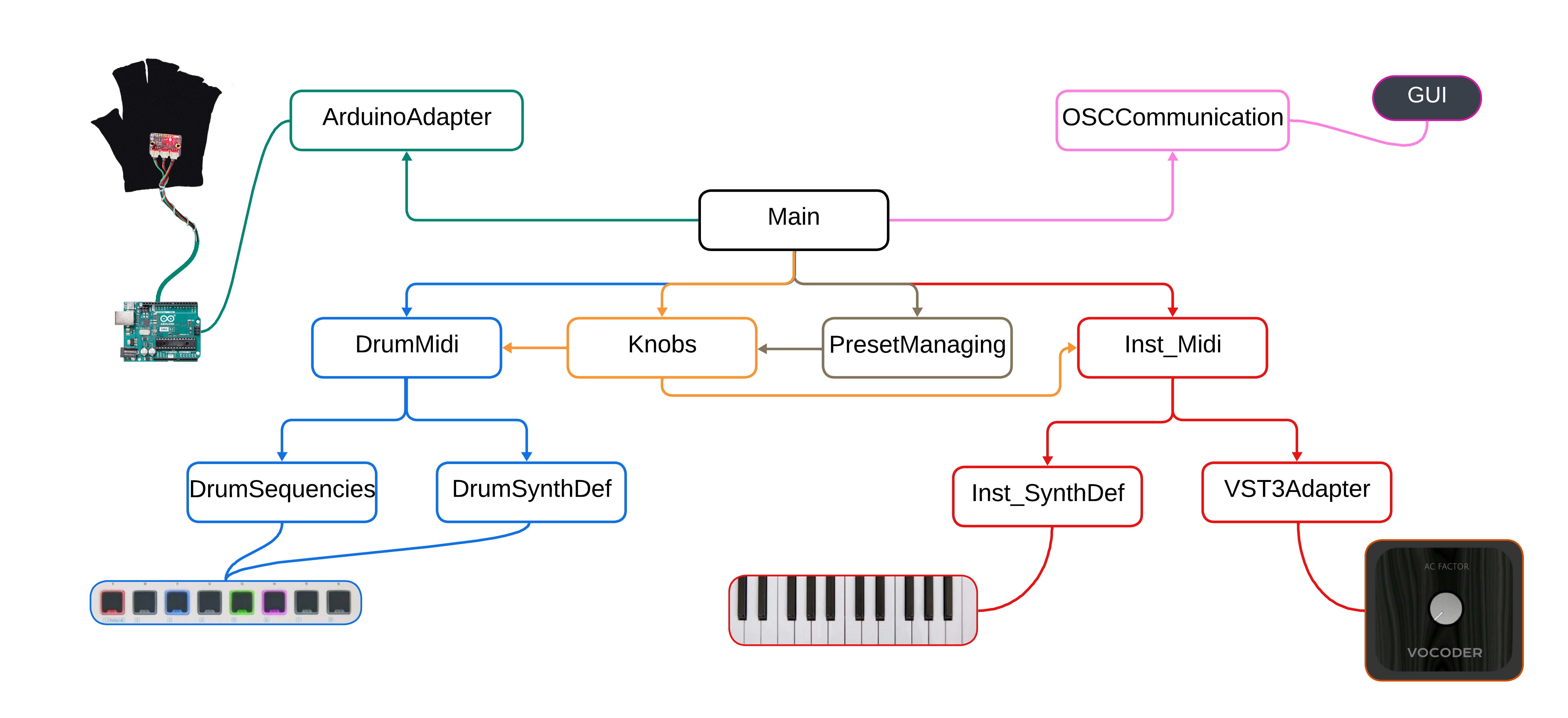
2.3 Implementation details
To implement the system, we aimed to separate functionalities into distinct modules and files as much as possible. This approach ensures independent operation, improving maintainability and code reusability. As shown in the following diagram:
- Blue modules: handle the rhythm section, processing MIDI inputs, defining which sounds to play, and setting percussion sequences.
- Red modules: handle MIDI note management, including processing of MIDI note inputs, defining synth sounds, and forwarding notes to the vocoder.
- Orange and gray sections: represent knob and preset management. When a user selects a new preset, the knob module updates all “knob values” (system parameters), which propagate to all other modules. In addition, the knob module handles MIDI CC inputs.
- Green module: the ArduinoAdapter module, which receives hand tilt values and applies them to the system.
- Pink module: the OSCCommunication module, responsible for receiving user mouse inputs and updating the GUI to display the system state on screen.
2.4 Interaction with accelerometer and Arduino
As for the glove implementation, input management is almost entirely handled in SuperCollider. However, the data received in SuperCollider are not the raw 3-axis accelerometer data. The accelerometer detects acceleration along the three Cartesian axes, while SuperCollider receives acceleration relative to hand orientation. To perform this conversion, we used formulas typically employed for managing drone orientation in flight (source).
2.5 Communication between SuperCollider and Processing
Processing creates a graphical user interface (GUI) that allows users to control sound parameters, which are sent to SuperCollider via the Open Sound Control (OSC) protocol. SuperCollider processes these inputs to produce audio and can send updates back to Processing for dynamic GUI adjustments. This interaction is illustrated in the following diagram:
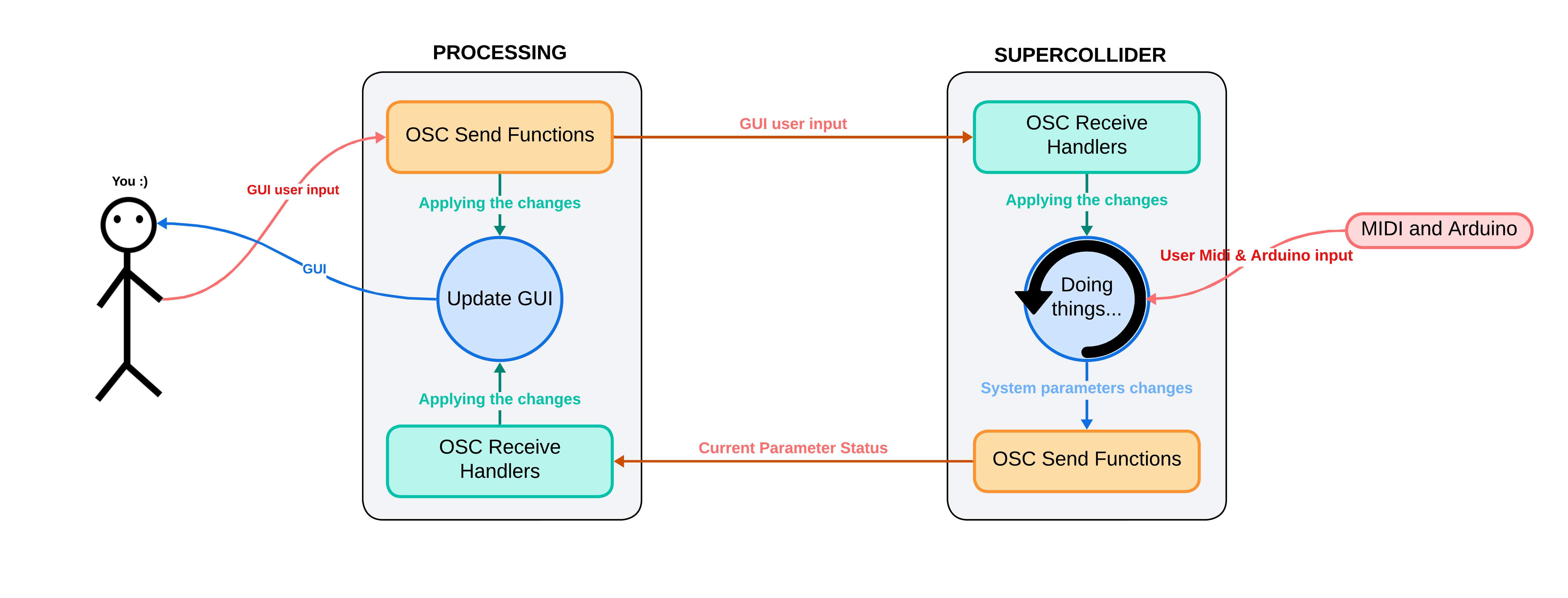
Below, we describe the roles of SuperCollider and Processing in handling the GUI and their communication methods.
2.5.1 Processing
Processing generates the GUI, including buttons, sliders, and knobs to control parameters such as volume, low-pass filters (LPF), instrument selection, octaves, control pedals, accelerometers, and presets. Excluding initialization and support functions, the code can be grouped into the following main sections:
- Communication management with SuperCollider:
- Sending OSC messages: the code handles sending OSC messages to SuperCollider to communicate various parameters. Functions send selected instrument names, control parameters such as mono state, volume, low-pass filter (LPF) frequency, BPM, vocoder volume, and Vocoder GUI state. In addition, they send selected octaves and accelerometer values.
- Receiving OSC messages: when OSC messages are received from SuperCollider, the GUI is updated accordingly. This includes updating knobs, sliders, and labels with the received control values and states, such as mono and GUI buttons.
- User input handling: the GUI allows users to interact with various controls. Buttons allow changing instruments, octaves, control pedal settings, accelerometers, and presets. Each button has a listener that changes background color and sends an OSC message to SuperCollider. Sliders and knobs allow adjusting parameters such as BPM, vocoder volume, overall volume, and filter frequencies, sending selected values to SuperCollider when they are changed.
- GUI update: the code graphically updates the user interface in each frame, drawing shapes and logos on the GUI window.
2.5.2 SuperCollider
In SuperCollider, we can divide communication management into the following main sections:
- Receiving OSC messages: the code handles receiving OSC messages from Processing via OSCdef, which defines various handlers to process received messages. These handlers update the corresponding variables based on received messages. They handle various aspects such as instrument selection, mono control, volume, low-pass filter, drum sequence BPM, octave selection, vocoder management, control pedal and glove mapping, and preset selection.
- Sending OSC messages: the ~updateGUI function sends OSC messages to Processing to keep the GUI updated. This function sends information about instrument volumes, low-pass filter cutoff frequencies, selected preset, selected instruments, mono state, drum sequence BPM, current glove state, vocoder volume, vocoder editor state, control pedal mapping, and selected octaves.
- GUI update routine: the ~guiRoutine ensures the GUI is always synchronized with the current parameter states by executing the ~updateGUI function every 0.1 seconds.
3. Guitar module
This module was implemented in SuperCollider. We called it “Guitar” because that is how we used it, but technically it could be used with any input signal from a microphone. We paid particular attention to the choice of the interface (MMA-A) to ensure stable conversion, and of the microphone (4099), a precise supercardioid, both by DPA Microphones.

3.1 The algorithms
A good starting point was studying the UGen SoundIn.ar and the code found in the examples included in the SuperCollider documentation. For our purpose, we decided to always have a mono input and a stereo output (or at least centered).
3.1.1 Bass synth
Using the UGens Pitch.kr and Amplitude.ar, together with SoundIn, allows stable tracking of the input signal which, when assigned as the frequency parameter of a UGen such as SinOsc.ar, in turn generates a stable and controllable output. At first, when playing single notes, we tuned it straight (1.0) and by octaves (0.5 lower, 2.0 higher), but we soon discovered some interesting effects:
- The coefficients used had to be precisely adjusted to compensate for the initial detuning of the strings being played and the slight delay of the output. Accidentally playing more than one note, the resulting pitch would be attributed to the loudest note being played, thus enabling a polyphonic input.
- The latter gave us the idea to redesign the algorithm to play a synthetic bass line together with clean chords or arpeggios. Straight tuning was adjusted to a more effective value of 0.994, with the higher octave at 1.985 and the lower octave at 0.497. Formant.ar was used instead of SinOsc for a more synthetic result.
- To refine the bass result, we decided to add a release time in Amplitude.ar and add a low-pass filter after the SoundIn for the treated result, to be added to the output and balanced with chords and arpeggios from the input.
3.1.2 Stereo guitar effects
Pitch effects on the market (Chorus, Flanger, Phaser) invariably treat the entire guitar signal, adding muddiness to the lower frequencies. Having added the low-pass (LP) filter on the input, we inverted its result to present the low registers intact at the center of the output image, and we added a high-pass (HP) filter to collect the signal (mid and high registers), to be cyclically detuned from left to right (L-R). LP and HP were compensated in a near Linkwitz-Riley configuration, so as not to overlap the signal bands. The L-R detunings were obtained by setting two delayed SinOsc with two arguments “rate @~0.1” and “depth @~6”, as in this example:
DelayN.ar(highSig, 0.5, SinOsc.kr((rate + 0.3)).exprange(depth*0.012, rate*0.030)*0.1);
The final result is a stereo Chorus (almost a Flanger), with a steady and clean low register in the center of the image. Finally, for our demo, we implemented a control interface in which we assigned the three required sounds: Clean, Chorus, and (Clean with) Bass.
You can find more info on GitHub.